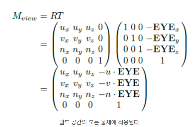
렌더링 파이프라인


랜더링 파이프 라인

  • 렌더링 프로세스 ( https://m.blog.naver.com/undergrd/220396106936 )
    • 렌더링 프로세스 : 3D vector data를 2D pixel data로 변환하는 과정
    • 래스터화rasterize : 3D vector data를 2D pixel data로 변환하는 행위
    • Process
      1. 전처리
        1. ray tracing
          1. 지오메트리 ( 넙스, 서브 디비전, 폴리곤 ) 정보 → 삼각폴리곤으로 변환 ( 테셀레이션tessellation )
            1. Approximation _ description
              1. 넙스nurbs/서브디비전subdivision은 면이 수학적으로 기술되어 있어, 곡면이라도 적은 양의 정보로 곡면을 자연스럽게 기술할 수 있음
              2. 그러나 테슬레이션 과정에서 온전히 삼각폴리곤으로 변환하려면 폴리곤 수가 지나치게 많아 짐
              3. 그래서 인간눈의 인지영역을 기준으로 "타협"하는 과정 approximation
            2. Approximation _ Type : 표현 방식(주로 벡터형식)
              1. surface(nurbs)
              2. curve
              3. trim
              4. subdivision surfaces
              5. polygon : 삼각형
              6. displace
            3. Approximation _ Technique : 면 분할 규칙
              1. Parametic(UV) : UV 분할 ( 평균등분 U분할수 x V분할수 )
              2. Regular Parametric(UV) : a와 동일하되, 곡률을 면적기반으로 균등화 시켜줌
              3. Length : tessellation된 폴리곤 edge의 길이 ( min / max 길이를 설정하는 형태, polygon edge 중 하나라도 min이하 혹은 전부 max이하 일때까지 )
              4. Distance : tessellation 전과 후의 위상차
              5. Angle : 인접한 폴리곤 사이의 노말 각도 차이
              6. spatial = length / curvature = distance + angle / LDA length + distance + angle
            4. Approximation _ technique additional
              1. 3D space 기반
              2. Resterized view 기반
            5. Approximation _ Style : 면을 분할해 나갈지

Grid / Tree / Delaunay

2. pre sampling & map creation

3. sampling

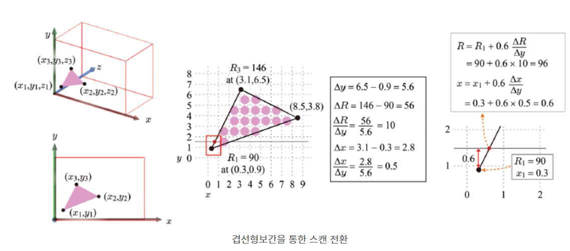
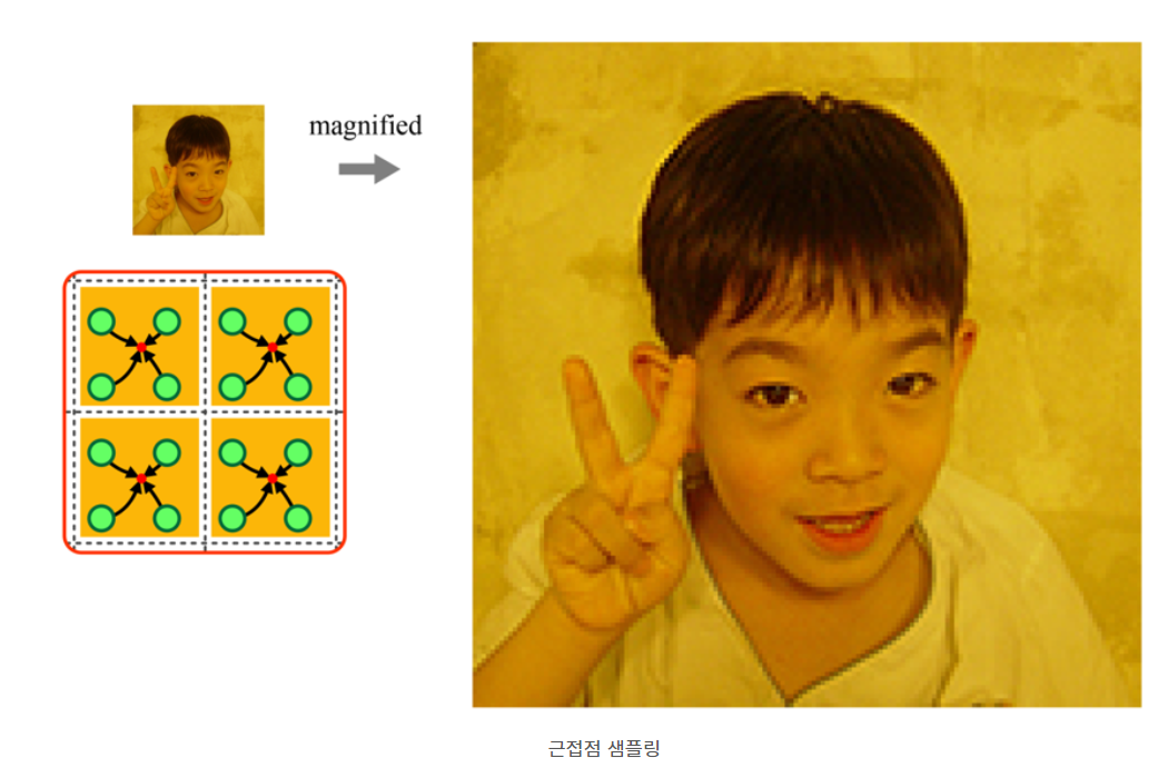
  • 공간sampling : 3d벡터들의 포지션값을 스크린의 "각 pixel 단위"에 투영하는 과정

Rasterize Sampling / Adaptive Sampling


  • 모션 블러
    1. 시간의 연속성으로 인해, "프레임 내 모션들"의 중첩을 블러처리 하는 과정
    2. time contrast : 1프레임 내 분할 횟수
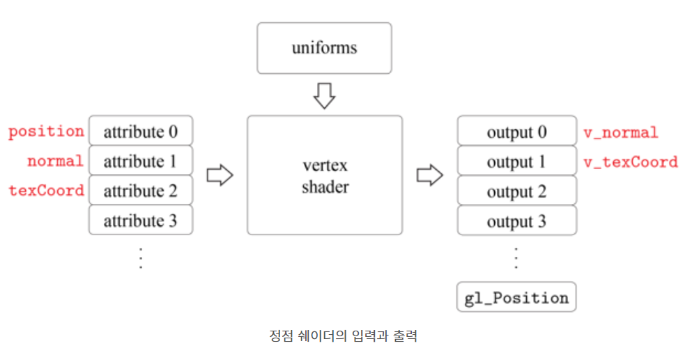
     

    1. shading calc
      1. ray casting 등 쉐이딩 연산 ( 라이팅, 마테리얼 등 )
    2. filtering : 픽셀수 < 샘플링수 → 샘플링값들을 픽셀에 계산하는 과정
    그냥 픽셀 내 샘플들 위상값 가중하여 평균내는 듯
    1.  


  1. saving frame buffer
  2. 후처리
  3. 최종 이미지


HSV to RGB

  • HSV
    • 색상(Hue) : H (hex(Core, Sub)를 float으로 대체)
      • Core색상 ( 1 ) 및 Sub색상과 그 비율 ( 0~1 )
      • ex)
        • Core색상 : R
        • Sub색상 : G
        • Sub가중 : 0.8
    • 채도(Saturation) : S
    • 명도(Value) : V
  • to RGB
    • Core색상 : S
    • Sub색상 : ( V + H(sub가중) * ( 1 - V ) ) * S
    • 남은색상 : V * S


'3D Graphics' 카테고리의 다른 글

기본 수학  (0) 2024.05.22
FBX 구조  (0) 2024.05.22
DX11 레퍼런스  (0) 2024.05.22
Graphics 개요  (0) 2024.05.22

Dot Product ( Inner Product )

  • result = ( Ax*Bx, Ay*By )
  • |result| = |A|*|B|*cos(theta)


Cross Product ( Outer Product )

  • |result| = |A|*|B|*sin(theta) (평행사변형넓이)
  • dir(result) = A와B가 이루는 면의 normal vector ( 오른손법칙 )
  • result = ( Ay*Bz-Az*By, Az*Bx - Ax*Bz, Ax*By - Ay*Bx )


Interpolation

Linear Inter. ( lerp ) : p(α) = p0 + α(p1 -p0)

Sphere Lerp ( Slerp ) : p(α) = ( qrt p0 ^  ( α ) ) * ( qrt p1 ^ ( 1 - α ) )


Affine Transform ( object basis - u, v, n )

SRT matrix ( scaling - rotation - translation ) for object space

Scaling / Rotation / Translation

만들땐 회전행렬 x3

역계산(값산출) 할떈 상위의 규칙에 따라 역행렬 산출-적용

( u*v = 0,  v*n = 0, n*u = 0 )


PreAttribute = position, normal


  • [R | t] ( rigid motion )
    • pre-post 합동

'3D Graphics' 카테고리의 다른 글

Graphics 개요2  (0) 2024.05.22
FBX 구조  (0) 2024.05.22
DX11 레퍼런스  (0) 2024.05.22
Graphics 개요  (0) 2024.05.22


FBX 구성 데이터 doc : https://help.autodesk.com/view/FBX/2019/ENU/?guid=FBX_Developer_Help_sample_programs_tutorial_programs_tut_scenetreeview_html


Help


help.autodesk.com


FBX Parser _ for JS/TS : https://www.npmjs.com/package/fbx-parser


fbx-parser

This parser will parse FBX text files and convert them into a JavaScript-Object structure.. Latest version: 2.1.3, last published: 3 years ago. Start using fbx-parser in your project by running `npm i fbx-parser`. There are 5 other projects in the npm regi

www.npmjs.com


FBX Parser _ for py : https://github.com/nannafudge/pyfbx


GitHub - nannafudge/pyfbx: Pure python FBX parsing library. No bindings, no external dependencies, no DLLs.

Pure python FBX parsing library. No bindings, no external dependencies, no DLLs. - nannafudge/pyfbx

github.com


'3D Graphics' 카테고리의 다른 글

Graphics 개요2  (0) 2024.05.22
기본 수학  (0) 2024.05.22
DX11 레퍼런스  (0) 2024.05.22
Graphics 개요  (0) 2024.05.22

https://github.com/walbourn/directx-sdk-samples/blob/main/Direct3D11Tutorials/Tutorial01/Tutorial01.cpp

https://github.com/kevinmoran/BeginnerDirect3D11


# include <d3d11.h>

# include <d3dcompiler.h>


D3D11CreateDevice(머신?) → CreateSwapChain(draw buffer? front buffer ↔ back buffer swap 관리자인듯)

  • SwapChain에 draw된 RenderTarget을 가져오고 ( SwapChain→GetBuffer , Device→CreateRenderTargetView )
  • depth stencil 가져와서 ( CreateTexture(DepthStencil flag )
  • 쿵짝쿵짝


Frame

  • context에서 clear rendertarget view
  • swap chain에서 present


render pipe _ shader config

  • vs Blob 생성 → 메모리 할당(D3DCompileFromFile) → vertex shader 생성(CreateVertexShader)
  • ps Blob 생성 → 메모리 할당(D3DCompileFromFile) → pixel shader 생성(CreatePixelShader)
  • inputLayoutDesces에서 cemantic에 대한 정의


예시

// Create Input Layout
ID3D11InputLayout* inputLayout;
{
    D3D11_INPUT_ELEMENT_DESC inputElementDesc[] =
    {
        { "POS", 0, DXGI_FORMAT_R32G32B32_FLOAT, 0, 0, D3D11_INPUT_PER_VERTEX_DATA, 0 },
        { "NORMAL", 0, DXGI_FORMAT_R32G32B32_FLOAT, 0, 12, D3D11_INPUT_PER_VERTEX_DATA, 0}
    };
 
    HRESULT hResult = d3d11Device->CreateInputLayout(inputElementDesc, ARRAYSIZE(inputElementDesc), vsBlob->GetBufferPointer(), vsBlob->GetBufferSize(), &inputLayout);
    assert(SUCCEEDED(hResult));
    vsBlob->Release();
}


render pipe _ draw call

  • D3D11_SubResource_data에 vertex 데이터 입력 ( { float[] } ) ← 3개마다 나눠서 x, y, z로 샘플링 ( flag : BindVertexBuffer ) → CreateBuffer
  • 동일하게 indces도 ( vertex index 기반 polygons ) ( flag : Bind_Index_Buffer )
  • constant buffer(createrbuffer) → resterizer state → depth stencil state
    • 상수버퍼 : 모든 버텍스에서 참조하는 상수 값. 전역변수같은 역할인듯. ex) object의 position 등. vs나 ps에서 상수버퍼 변수명 그대로 쓰면 됨
    •  
struct Constants
{
    float4x4 modelViewProj;
};
 
ID3D11Buffer* constantBuffer;
{
    D3D11_BUFFER_DESC constantBufferDesc = {};
    // ByteWidth must be a multiple of 16, per the docs
    constantBufferDesc.ByteWidth      = sizeof(Constants) + 0xf & 0xfffffff0;
    constantBufferDesc.Usage          = D3D11_USAGE_DYNAMIC;
    constantBufferDesc.BindFlags      = D3D11_BIND_CONSTANT_BUFFER;
    constantBufferDesc.CPUAccessFlags = D3D11_CPU_ACCESS_WRITE;
 
    HRESULT hResult = d3d11Device->CreateBuffer(&constantBufferDesc, nullptr, &constantBuffer);
    assert(SUCCEEDED(hResult));
}

'3D Graphics' 카테고리의 다른 글

Graphics 개요2  (0) 2024.05.22
기본 수학  (0) 2024.05.22
FBX 구조  (0) 2024.05.22
Graphics 개요  (0) 2024.05.22


모델링

폴리곤 기반 메시


좌표 변환

TRS 매트릭스

Basis


orthonormal, standard / non-orthonormal, non-standard / orthonormal, non-standard

orthonormal ( basis ) : local space의 각 dimension축(basis) 이 독립적인지 ( 직교인지 ) x 각 dimension축시 단위벡터인지 여부

standard : local space의 각 dimension축이 기준 직교좌표계의 축과 일치하는지 여부


렌더링

렌더링 파이프라인

IM → VS → RS → FS(PS) → OM ( shader = program at GPU )


VS ( vertex shader )

  1. view transform
    world space → eye(camera)의 location & 3dimension space를 통해 camera space로 변환 {u, v, n, EYE}
    [Eye] = 카메라pos, At = 카메라가 보는 dir → [n], Up X n = u, u X n = [v]

  2. projection transform

    1. view transform
      world space → eye(camera)의 location & 3dimension space를 통해 camera space로 변환 {u, v, n, EYE}
      [Eye] = 카메라pos, At = 카메라가 보는 dir → [n], Up X n = u, u X n = [v]


    2. projection transform

      1. view transform
        world space → eye(camera)의 location & 3dimension space를 통해 camera space로 변환 {u, v, n, EYE}
        [Eye] = 카메라pos, At = 카메라가 보는 dir → [n], Up X n = u, u X n = [v]

중간 전달 과정


vertex array

attribute

  • position ( object space )
  • color
  • texture coordination ( uv mapping )

caculated

  • normal ( 자신을 포함한 polygon들의 normal 평균 )
    • tangent space ( tangent + bitangent ) 

index array

attribute

  • index in vertexarray

Polygon

attribute

  • normal
  • index array

calculated

  • normal ( position of vertexes )


Rasterizer

클리핑, 원근 나눗셈, 뒷면제거, 뷰포트 변환, 스캔 전환

클리핑 clipping

  • view frustum(절두체)에 걸치는 object를 clipping ( 절단면 반영하여 GPU가 오브젝트 재구성 )

원근 나눗셈 perspective division

사다리꼴을 직육면체 projection으로 변환 (projection transform)

뒷면 제거 back face culling

z축값 무시하고 폴리곤의 포함 버텍스가 시계/반시계 체크

뷰포트 변환 viewport transform

  • NDC(Normalized Device Coordinate) → 뷰포트(VPT)
  • 기준점을 중심에서 모서리로 옮김 ( 언리얼은 좌상단이 0, 0, 우하단이 1, 1 / [0, 1] 정규화 )

스캔 전환 scan conversion

  • 뷰포트(VPT) → Screen Space ( UV 2차원 공간 )
  • pixel을 기준으로 fragment를 생성하여 각 fragment의 attribute는 자신을 포함하는 poligon의 vertex들의 attribute를 보간하여 적용
    • dx12의 multi 머시기는 x4배수
  • color, normal, tangent 등 


프래그먼트 셰이더

  • 라이팅 / 텍스쳐링

텍스쳐링

  • 텍스쳐는 texel들로 구성
  • rasterize단계에서 보간된 attribute에 따라, 각 fragment가 참조할 texel coord를 판단  

표면 파라미터화 surface parameterization

  • UV 매핑
    • 패치 ( UV상의 프래그먼트 )
    • 차트 ( UV에 입혀질 이미지 )
    • 아틀라스 ( 여러 차트를 커다란 텍스쳐에 모으는 것

기본적인 샘플링 예시


기본적인 Anti aliasing 예시

  • 밉맵 생성 ( 산술평균 기반 다운샘플링 )


라이팅

  • 퐁 모델 ( sum = diffuse + specular + ambient + emissive ) ( s는 light source의 RGB / m는 물체표면의 RGB )
    ox는 독립곱 ( r, g, b ) ox ( R, G, B ) = ( rR, gG, bB )

각도별 감쇄율 조절 필요시, exp(cos, n) 처리 ( specular )
간접조명 ( ambient ) : n차반사를 통한 은은한 빛 ( input vector.direction = anywhere ) / 발광 ( emissive )
Pre-fragment Lighting ( l = light vectro, n = normal vector, v = camera space vector )


Z buffering

  • pixel에 buffer된 z값과, fragment의 z값을 비교 ( glEnable ( GL_DEPTH_TEST ) )
    stensil buffer
    • 후면버퍼에서 추가계산이 필요없는 픽셀 저장
    alpha값 적용


기타

normal mapping

R = ( normal_x + 1 ) / 2 => normal_x = 2R - 1

G = ( normal_y + 1 ) / 2 => normal_y = 2G - 1

B = ( normal_z + 1 ) / 2 => normal_z = 2B - 1

=> 그래서 폴리곤의 노말벡터를 따라가는 중립은 ( 0.5, 0.5, 1 )

아마 texture가 적용된 polygon의 tangent space에서의 normal값을 world space로 transform하는듯


shadow mapping

  • shadow mapping을 위한 ray tracing 단계가 별도로 존재
  • ray내 충돌체들(fragment단위)간에 light와의 distance 비교를 통해 shadow 적용여부 체크 ( nearest point sampling )
    • light source → 각도별 lay 단에서, 양자화된 각도별 nearset distance를 구함
    • 이후 영향범위 내 각 object의 texel에 대한 light의 가려짐 판정 시, light - texel distance VS buffer nearest distance 비교하여 차이가 나면(nearest가 더 작으면) 가려짐 판정


자글그림자의 원인

  • 충돌지점좌표는 연속적인 그림자인데 반해, 비교대상 ( 버퍼에 저장되어있는 타겟 ) 은 양자화된 texel단위이기 때문에, 해당 texel의 영역내에있는, 보다 멀리있는 점들은 연속표면임에도 덮임판정을 받음
  • 그래서 bias를 무시할 범위를 파라미터로 관리함


Ambient occlusion

  • 샘플 지점이 주변으로 부터 얼마나 닫혀있는 지
  • Normal vector 기준 지정된 비산각(spread)/유효거리(max distance) 내 probe ray를 통해 object
  • 오브젝트에 hit된 probe ray 비율에 비례하여, Bright ↔ dark
  • Property
    • sample : probe ray 횟수 ( spread와 합해서 밀도 )
    • birght/dark :
    • spread : 프로브 비산각 범위
    • max distance : 유효 프로브 거리
    • reflective : surface의 노말이 아니라, 입사각 기준
    • fall off : 감쇠효과 (거리기준)

'3D Graphics' 카테고리의 다른 글

Graphics 개요2  (0) 2024.05.22
기본 수학  (0) 2024.05.22
FBX 구조  (0) 2024.05.22
DX11 레퍼런스  (0) 2024.05.22

+ Recent posts